
Circuit Innovations
Taking your electronics ideas and turning them into reality
| Home |
| Design Service |
| Kits and Products |
| Film and Television |
| Beginners Corner |
| Surplus Stock |
| Price / Ordering Info |
| Contact Us |
| Terms and Conditions |
| Links |
| About |
|
Circuit Innovations 24 Leasmires Avenue Easingwold York. YO61 3DU UK |
 |
| Beginner's Corner > Components > Transformers |
|
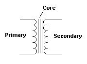
The basic principle of operation of all chokes and transformers relies upon the fact that electricity and magnetism are closely linked to each other. A wire carrying an electric current will produce a magnetic field around the wire. Conversely, a wire placed into a magnetic field or moving through a magnetic field will have an electric current induced in it. Transformers The transformer is used to convert one voltage level to another or to provide isolation between two electrical circuits. Note that the transformer only works with alternating current and will not work with direct current. The simplest form of transformer is shown here. The two windings are known as the primary and the secondary. There is no direct electrical connection between the primary and secondary windings. An alternating voltage applied to the primary winding will cause a corresponding alternating magnetic field to be produced in the surrounding area. As mentioned earlier, placing a wire into this magnetic field will cause a current to be induced in the wire. In this case, the wire is the secondary winding of the transformer and an alternating voltage will be produced across the winding. The size of the voltage is directly proportional to the number of turns of wire in the windings and is known as the turns ratio. For example, a transformer with 100 turns on the primary and 10 turns on the secondary will have a turns ration of 100:10 or 10:1. This means that the secondary voltage will be 1/10th of the primary voltage. The reduction in voltage will be matched by a corresponding increase in the amount of current available. This means that if our transformer with a 10:1 turns ratio was passing a current of 1 amp into a load connected to the secondary winding, the current in the primary winding would be 1/10th of this value. The two (or more) windings of the transformer are wound around a core. The core helps to improve the strength of the magnetic field produced by the primary winding. In low frequency transformers for general purpose power supplies the core is usually made from soft iron. Usually this is made up from several thin sheets or laminations which are stacked together. The reason for the laminations is to reduce the eddy currents induced in the core which would be greatly increased if the core was made from one solid block. Simply speaking, the eddy currents reduce the transformer efficiency and waste power. High frequency transformers, such as those used in switch-mode power supplies use a ferrite material for the core. Each individual particle of the ferrite material acts in a similar manner to the individual laminations in an iron core.
Centre-tapped secondaries are often used in power supply circuits. The main advantage is that a full wave rectified output can be produced by only using two diodes instead of the usual four. This results in an improvement in efficiency as there are only two diode drops in the circuit instead of four.
|
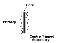 Secondary Windings The transformer can have different forms of secondary winding depending upon the application in which it will be used. The simplest form is shown at the top of the page. Another common variant is the centre-tapped secondary winding. This winding actually has three connections; one from each end of the secondary and a third connection from a point mid way along the winding. The voltage at the centre point will be half of the voltage that appears across the full secondary winding. Moving the centre tap from it's mid position will cause a corresponding change in the voltage in a similar way to the wiper connection of a potentiometer varying the voltage. (more of this feature later).
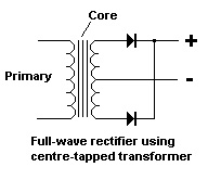
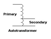 Autotransformers Most transformers are used to provide a voltage change and also isolation between the primary and secondary circuits. The autotransformer provides the voltage change but does not isolate the primary and secondary voltages. The transformer consists of only one winding, similar to the secondary of the centre-tapped transformer above. The output voltage is proportional to the ratio of the number of turns on the secondary part of the winding compared to the total number of turns on the winding. These transformers are mainly used to change supply voltages where isolation isn't required. For example, changing 110v ac to 240v ac to allow equipment to be used in different countries with different mains supply voltages.
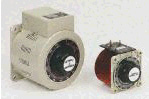 Variac A variation of the autotransformer is the variable transformer or Variac. This consists of a sliding contact on the secondary winding so that different voltages may be tapped off. They are mainly used in equipment testing and allow the supply voltage to be gradually increased from zero while the test engineer checks for possible faults or short circuits.